![]()
Here are the operational instructions for the Spitfire Electric arc etcher in a couple of formats:
Operating Instructions
for the
Gorton Spitfire Etcher
Copyright, 2004 - 2015
Richard Gorton
rcgorton@verizon.net
The instructions below were transcribed from the originals, which were (are) glued to the inside lid of the Spitfire Etcher box. The logo above is pretty close to the actual size (2 1/4" diameter) but the image is significantly retouched after scanning (the original had a fair amount of the paint chipped off), with the metal showing. In the center of the logo is an outline of one of the electrodes; the electrode on the logo is also close to actual size (15/16" long), and they have "GORTON" etched on one of the flat surfaces. Patents were filed on parts of this kind of mechanism in 1942, so it is a reasonable assumption that this device appeared on the market during or shortly after WW II. Unfortunately, I do not have an etcher at this point in time (May 2004) but if I manage to find and acquire one, I'll update this with better pictures and information about the lubrication points.
OPERATING INSTRUCTIONS
THE GORTON SPITFIRE ETCHER WILL OPERATE ON 110 VOLTS, 60 CYCLE, SINGLE PHASE CURRENT ONLY. CAREFULLY CHECK THESE FIGURES AGAINST THE POWER SUPPLY.
Upon removing the etcher head from the case for the first time, carefully clean the packing grease from the shank.
Remove cutter spindle from the engraving machine and insert the shank of the etcher head in the cutter head bore so that tbe rear of the main body of the instrument is nearest the column. Pull up the screw or screws fairly tight to insure a good electrical connection.
Insert an electrode of the proper size in the electrode arm. Pull the thumbscrew up snug.
Plug the power input cable into the supply line.
Throw the toggle switch on the control panel to "ON". The pilot lamp should light and the mechanism in the etcher head should emit a subdued buzzing sound. The electrode should be vibrating vertically.
Depress the feed button located on top of the etcher head. The electrode arm and electrode should drop downward 3/8". Upon releasing the feed button the electrode and arm should move to the uppermost position again.
The actual etching is performed as follows: With the work piece arranged about 3/16" below the end of the electrode when the feed button is up, the toggle switch is snapped to "ON" starting the etcher head motor. Rest the butt of the palm of the left hand on the projection of the case immediately ahead of the shank in such a manner that the thumb and index finger partially encircle the shank. Depress the feed button all the way with the side of the left thumb. The electrode strikes the work piece and starts the arcing. The pantogragh style should be moved over the master copy with the right hand in a deliberate manner while etching. A too rapid movement of the style will result in the etching appearing as a succession of dots rather than a continuous line. When a letter is completed, the left thumb is raised permitting the feed button to return to the "up" position raising the electrode from the work piece. The style is then shifted to the next letter. Again the feed button is depressed permitting the electrode to fall on the work, and so on. The motor runs continuously, coming to rest only when the main switch on the control panel is off.
MAINTENANCE
The etching current control switch provides 10 etching current densities from No. I at "LOW" to No. 10 at "HIGH".
The electrode diameter having been selected as most suitable for the work, should be supplied with as much current as will give the desired depth of etch consistent with reasonable economy of electrodes.
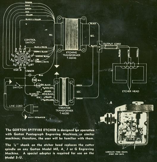
The only attention required on the port of the operator is the occasional lubrication of the four points (see photo) where frictional metal to metal engagement occurs; and replacement of the pigtail.
TO LUBRICATE: Switch off the etcher motor. Remove the two screws holding the front cover plate. The plate will drop down and rest with its slot embracing the electrode arm. Depress the feed button all the way. This lowers the electrode arm permitting the plate to be removed.
With a small wire oil may be readily applied to the points designated in the photo. Use a light non-gumming oil, Wipe off any excess.
The light flexible cable leading from the bakelite terminal block to the electrode arm is the only port. other than the electrodes, which is considered perishable. This cable conducts the etching current from the input to the electrode arm. As the arm moves, this cable flexes. The constant flexing, after a time, crystalizes the copper strands causing them to break. This light cable or "pigtail" is fitted at either end with tips which fit into receptacles provided for them in the terminal block screw and the electrode arm.
Failure to obtain an arc at the electrode is usually due to a break in the pigtail. This may be readily checked as follows:
Stop the motor, remove the front cover plate, touch a screw driver to the instrument case then to the terminal screw A (see photo) . If a spark occurs, then touch the screw driver to the case and the electrode. If no spark occurs, the pigtail is broken. The fit of the pigtail plugs in the receptacles MUST BE SNUG. The plugs are split permitting adjustment to provide a snug fit. The operator should lubricate the instrument every few days, and replace the "pigtail" when necessary. In case of failure of low voltage power supply, the electrician should first check the fuses, then inspect the transformer, for disconnected wires. If this does not disclose the cause of failure, return the entire unit to the factory.
GEORGE GORTON MACHINE CO.
RACINE, WISCONSIN, U. S. A.
FORM No 1709
Copyright, 2004 - 2015 Richard Gorton - rcgorton@verizon.net